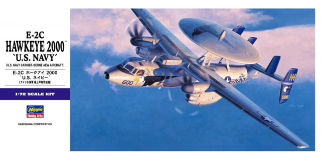
Northrop Grumman E-2C Hawkeye 2000"
Hasegawa (01561)
1:72
Started: Jun 2009
Finished: Dec 2009
Link to Gallery
The Northrop Grumman E-2 Hawkeye is an American all-weather, carrier-capable tactical airborne early warning (AEW) aircraft. This twin-turboprop aircraft was designed and developed during the late 1950s and early 1960s by the Grumman Aircraft Company for the United States Navy as a replacement for the earlier, piston-engined E-1 Tracer, which was rapidly becoming obsolete.

The E-2 was the first aircraft designed specifically for its role, as opposed to a modification of an existing airframe, such as the Boeing E-3 Sentry. Variants of the Hawkeye have been in continuous production since 1960, giving it the longest production run of any carrier-based aircraft.
The E-2 also received the nickname "Super Fudd" because it replaced the WF (later E-1) "Willy Fudd". In recent decades, the E-2 has been commonly referred to as the "Hummer" because of the distinctive sounds of its turboprop engines, quite unlike that of turbojet and turbofan jet engines. In addition to U.S. Navy service, smaller numbers of E-2s have been sold to the armed forces of Egypt, France, Israel, Japan, Mexico, Singapore and Taiwan.
KIT OVERVIEW - Hasegawa 1:72 E-2C Hawkeye 2000 (01561)
I have always liked the shape of the Hawkeye and there is something very "workhorse" about this (and its cousin the C-2 Greyhound) that appeals to my passion for "working aircraft". Hasegawa has delivered us a fantastic kit in 1/72 scale, with the only thing missing being a wingfold.

Normally, for 1/72 I would have posed this model in flight on a stand, but I've not seen any convincing method for making prop models look realistic in flight. So, if the model had to be earthbound, why not put it on a base with some figures. When I saw that Wolfpack had just released a wingfold set (and Luckymodel had them in stock) the project took shape in my head.
BUILD - Hasegawa 1:72 E-2C Hawkeye 2000 (01561)
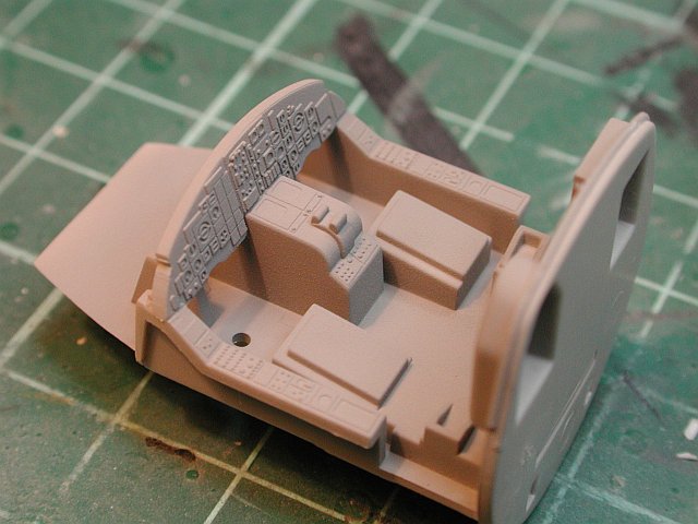
The fairly new Squadron Walkaround will be my main source of reference for this build, starting with the seats. The back cushion needed a little re-shaping and some simple lead foil seat belts added. This will be the only enhancement to the cockpit as Hasegawa have done a pretty good job and you won't see much of it anyway.)

To make life easier for the modeler (to remove ejection pin marks etc), the nose wheel well has been molded in three parts. An excellent idea (especially for a 1/72 model)

The cockpit tub has been assembled and painted. I plan to use the kit decals for the front and side instrument panels
The main clear part is being test fitted to the fuselage. The bulged side panels have been molded separately by Hasegawa which will easy painting as these are highly tinted and reflective

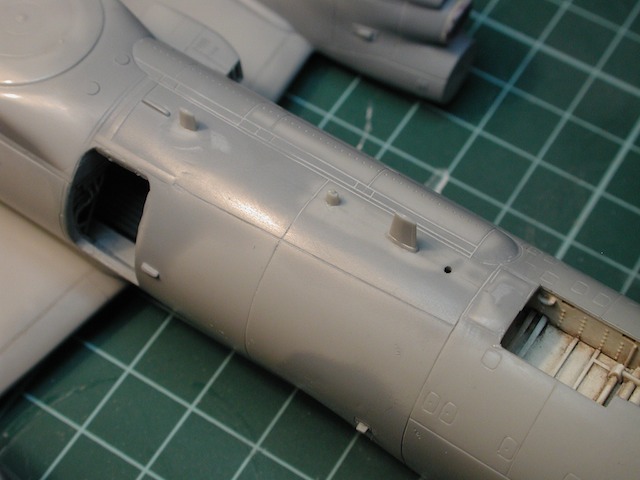
Whilst the cockpit paint was drying, I turned my attention to the engine nacelles. Quite a lot of work to be done here. Note the prominent ejection pin marks. I am going to resist the urge to add extra detail here (eg ribbing, piping). I rather put the effort into figures etc for the deck base

Some Tamiya basic putty will take care of the pin marks

The main gear doors are nicely done, with nice locating pins to enable them to be attached accurately during final assembly. I did think it was odd that the mounting brackets are not long enough to slot into the wheel well holes. A quick fix for that was to extend their length with some 30x30 thou rod. I'm hoping it will do the trick

I was a little disappointed at the lack of intake trunking on the engine. I guess this is 1/72 so I should not be too critical. One option was to using FOD covers, but rather than be lazy, I decided to look for a better solution

Some 1/4" tubing is a good fit (with some trimming) for the intake trunking. Once glued and filled this should come up nicely. Lets hope you can see it

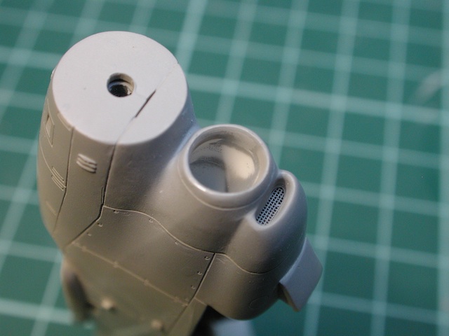
While consulting my engine intake references, it became clear that the small oval intake below the engine intake has a protective screen mesh. Here I have used a knife to open up the space inside the intake and cut some fine mesh to fit

Any improvement to be sure, but again how much will be visible on the finished model, only time will tell

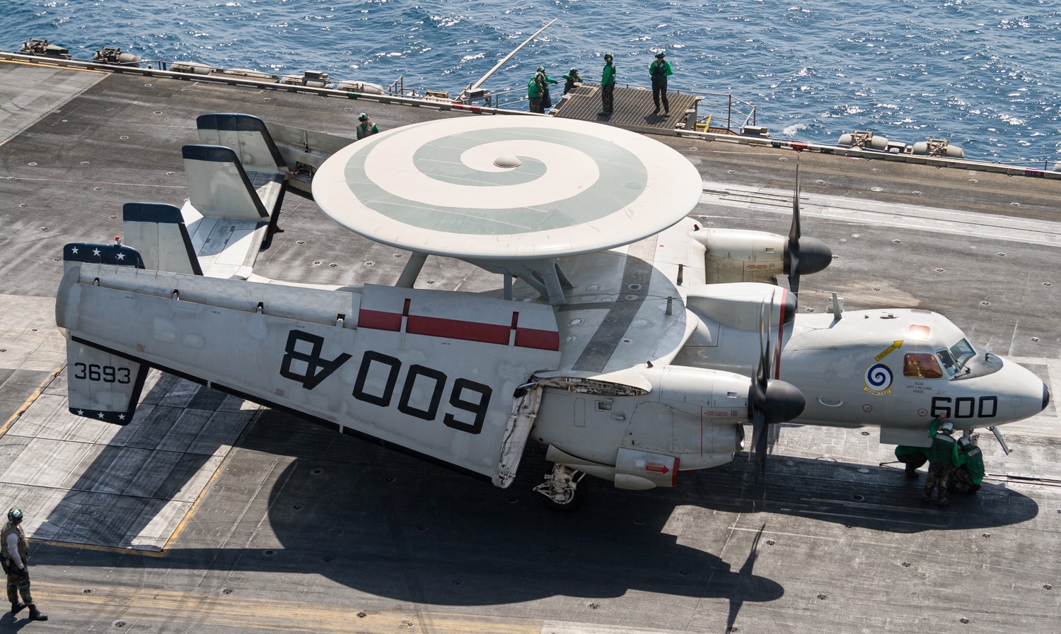
While researching photos of E-2's on the deck of the carrier, one thing they all had in common was that the crew access door was always open. Hasegawa do not give you an open door (pity) but do look as it they have catered for those (like me) who want to open it up

Notice how the interior floor is lowered in line with the door bottom. This means if we cut the door out, the floor will already by in the right spot (well some of it will). Good thinking Hasegawa

As I will need to scratchbuild the door (which double as the steps), I decided to use the kit as a template before I hacked it up. Some copper sheet has been cut and shaped to size and is seen here laying on the model

With a deep breath, its time to get rid of that closed door. Chain drilling works well and makes short work of the fairly thick plastic in this area

Once the holes are drilled, a knife is used to cut the small sections between. Simple but effective

Finally, a knife and metal files are used to cleanup the opening to match the panel lines. You can clearly see what I was referring to earlier about the interior floor near the door. Next step will be to scratchbuild enough interior to fill this hole

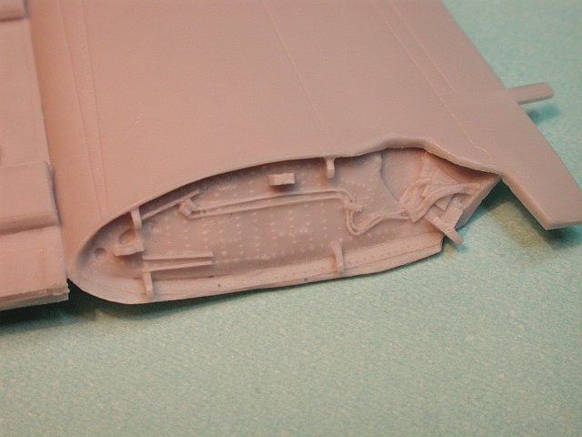
With the external door now opened, I need to scratch build enough of the interior so that anyone looking thru the door cannot see beyond. First thing I need to do it lower the "floor" to match the level of the bottom of the door opening. The hatched areas are to be removed

Looking down from above, you can see that some plastic needs to be removed from both fuselage halves. This section will form the corridor that runs the length of the E-2

Once the unwanted sections are removed, a new floor needs to be fashioned. Here I am using some ribbed plasticard. Again, clearly marking the sections that need to be removed, saves you from making the wrong cut

With the floor held temporarily in place with tape, I have built the starboard corridor wall. Essentially the only remaining scratch building is on the port side, either side of the entry door

When viewed from the outside, you can see the corridor wall

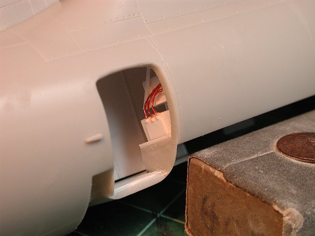
Work has continued on the interior (as I need to finish this so I can close up the fuselage !!). Using the Squadron Walkaround #63 book as reference, I have scratchbuilt the bulkhead and equipment shelves on either side of the door

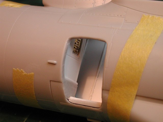
A small Reheat PE placard (which is technically 1/48, but looks just fine) has been used to simulate a control panel which is located just inside the forward part of the doorway

When viewed from outside (with the fuselage halves joined) its starting to give the impression of more than just an empty shell
This is the angle from outside when viewed from the front. I need to make some equipment boxes to place on the shelving next

You can see the basic idea of this scratchbuilding when viewed from the top. Of course this angle won't be visible when complete as the wing will be in place

When surfing the usual model sites the other day I found out that Wolfpack Design had released a wingfold set for the Hasegawa kit. As I had toyed with the idea of doing this myself (and quickly decided against it due to my laziness) and lets face it, this model was way past the "out-of-the-box" status, I figured for US$27.99 from LuckyModel, what the heck.
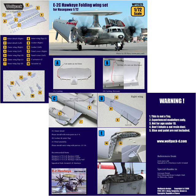
Here is the entire contents of the conversion set. The resin is very well molded, being for the most part bubble and blemish free. You will notice that Wolfpack have provided the entire outer wing sections. This is good for several reasons.
- You don't have to be so careful when cutting the kit wing as the outer section will be discarded
- The small door on the lower wing that contains the tail locking mechanism has already been built
- The interior detail of the wing join has already been mated to the outer wing

Several small parts are provided and are as follows:
- Right top are the two tail locking parts that come out of the lower wing when folded
- Right bottom are the open doors for the tail locking parts
- Left top are part of the wing fold supports (non load bearing thankfully)
- Left bottom are also part of the wing fold, being hydraulic struts

When the wing folds on the E-2, the flaps are split into two sections. Wolfpack have done that work for us as well

As I could not find any clear close up pics of the resin before I purchased it, I thought some detailed shots here might help someone else. For 1/72 it really is quite nice
The inboard "plug" that will be fitted to the fixed part of the wing, once I have cut the kit part

As with all resin sets, first job is to remote the molding blocks. Here I am using my trusty Tamiya scriber to remove the bulk of the resin quickly

To finish the job, a quick run thru with the 5thou PE saw did the trick. Notice that the wing leading edge still requires some considerable cleanup

As I was preparing the flaps, I noticed that they were curved. I suspected that this was not correct and when compared with the kit parts, I was right. I'd guess that as part of the molding process, the silicon mold was not held perfectly straight and the result was bent flaps. I'll see how hard it is to straighten these a little later with hot water

After the excitement of the wingfold (yes I do still sometimes get excited at age 44), I resisted the urge to start hacking the wings up and returned to the interior scratchbuilding. The equipment shelves now have been filled and some basic cabling added to give that "busy" look

When seen from outside, the result looks suitably convincing (well I think it does anyway)
While I was on a roll, I decided to start work on the door. The biggest problem was going to be building the interior frame. I tried to "bend" some 40x40 thou square rod, to no avail. So I decided that I could use the door itself to trace with pencil the correct shape and then cut it out. This provided to be quite easy and the result was great
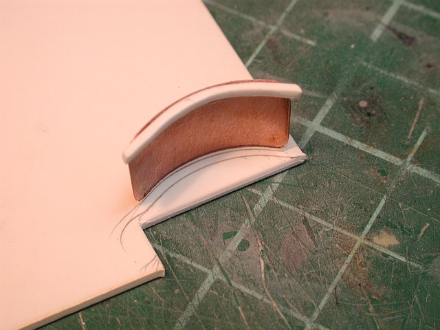
The framing was glued using CA super glue to ensure a solid bond between the plastic and copper parts

Last thing to do for the time being is to drill the attachment holes for some 12 thou brass rod. This rod will act as the hinge for the door. I won't build the steps themselves as yet because I want to set the angle of the door once I have the model on it landing gear

I was pretty keen to see how the Wolfpack wingfold performs. Once the wing was cut (more on that in a sec), I could see that the resin parts fitted very well. Of course some trimming and adjusting was needed, but overall, I was quite happy

When you look at the Hasegawa wings, they must have intended to make it easier for modellers who want to cut and fold the wings. The trenches on both upper and lower wing sections are exactly where the wingfold cuts take place

Because Wolfpack provide a complete replacement for the outer (ie folded) wing section, I was able to cut the wing in such a way that the inner section remained un-damaged. The overcuts and knife slips on the outer section do not matter as this part will be discarded anyway
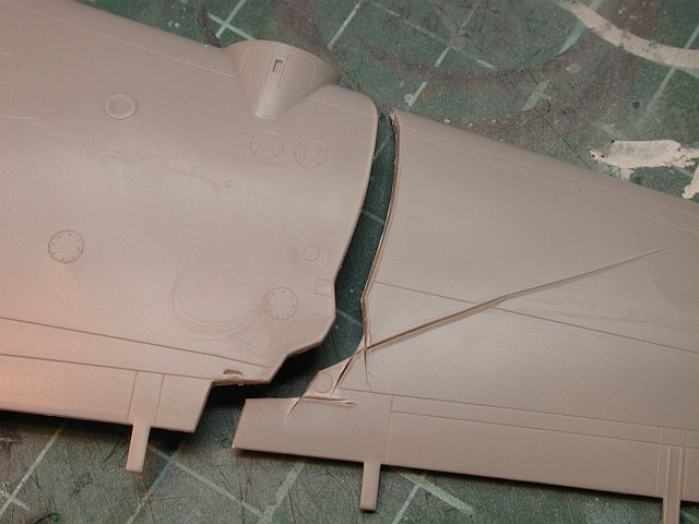
With the wing cut, a simple test fit of the resin wingfold "interior" highlighted that the thickness of the wing "skin" plastic would be a problem. The arrows here show the plastic that must be thinned considerably to obtain an accurate scale appearance

After some careful (and persistent) scraping of the wing with a sharp knife blade, the thickness is reduced to something that better approximates the real sheet metal used on the aircraft's outer skin. The arrows show that this scraping must be done for both top and bottom wing sections

Another view of the wingfold, from the bottom this time. The small visible gaps between the resin and plastic all but disappear when pressure is applied. I will clamp the parts when gluing to keep the gaps to a minimum

With the scratch-building complete for the aft-compartment near the entrance door, some paint is applied, some weathering and some small squares of 1200 grade wet n dry paper used to make up non-slip mats on the floor. The cockpit tub has also been painted and installed. As the radome of this model is quite large and sits well back on the fuselage, I am quite concerned about putting enough weight in the nose. Here you can see the lead sinkers glued behind and one in front of the cockpit. Lets hope its enough

Following all the trimming and test fitting, its time to glue the wingfold resin to the modified wing section. To give the strongest bond and allow time for adjustments, I like to use two part epoxy glue

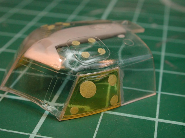
The E-2C has a clear window in the lower nose section thru which the landing lights shine. Hasegawa gives us the entire nose as a clear part. The window is shown here masked off with Tamiya tape

The interior of the nose has been painted and some Eduard PE lights has been added for the landing lights. The nose cone will be glued on next

Turning my attention to the engine intakes, I have now glued some suitably sized plastic tubing inside the intake lip to form the trunking. This trunking extends about 1.5 cm into the nacelle. Just long enough to give it some depth

Once the glue dried, I filled the larger gaps with milliput. Here you can see a home made sanding stick made from a smaller platic tube with wet n dry paper wrapped around it

The trunking is starting to blend into the lip. Some more filler is needed, and for that I will use Tamiya Basic filler. (followed by yet more sanding)

Hasegawa gives the option of replacing the wingtip molded in navigation lights, with clear versions. As my wingtip is now resin, the same principle applies. I was surprised with the poor fit of the part and have put it down to shrinkage of the resin wing section

After the super glue is dry, some filing and buffing/polishing brings the part back to a good fit

Here we see both wingtips completed. A far more realistic result than the plastic navigation lights

The tail of the E-2 is very unusual. Hasegawa has done a good job of molding all the raised detail in this area. The only fit problem I found was on the end of each side of tail boom. Quite a large gap resulted and I filled it with 10 thou card. This was later trimmed and sanded smooth

When the wing is folded, a small aux door on the lower wing opens and a locking bracket extends. This in turn is locked to the tail of the aircraft to stabilise the folded wings during taxi etc. During my test fitting of the wolfpack resin parts, I decided the bracket needed to sit higher (hence the small section of white card) and also that to help bear the weight of the resin wings, I would pin the brackets with brass rod. These are very small brackets, needing a very small drill and a very steady hand

Once complete and painted, this is the position will sit it. Of course the wing will be vertical and the bracket horizontal

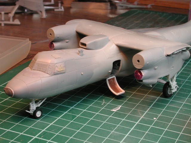
With the fuselage joined, its time to test fit the inner wing section and the large canopy clear part. As anticipated, only very minor adjustments were needed
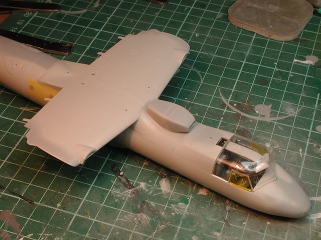
Hasegawa have molded the bulged sections of the side windows as separate parts. Its time now to glue them into position on the main canopy section. The side windows are heavily gold tinted on the real aircraft and I have simulated this using a coat of the Tamiya Clear Yellow on both the inside and outside surfaces

With the fuselage coming together, its time to start masking up. The crew windows and the APU exhaust shield are masked with Tamiya tape

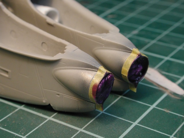
The intake trunking on each engine nacelle is now complete. Next step is some primer and then metallic for the intake lip
A coat of Alclad Stainless Steel cover the lip and will be masked when dry

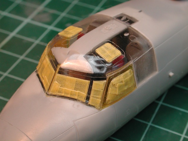
I decided I could no longer put off the masking of the canopy. As it involves lots of windows with rounded corners, I used the Waldron Punch Set to create small discs of Tamiya tape. These have been placed in the corners
Next step is to join the corners with small strips of tape. Notice how I changed my mind on the side window top left corner. I decided it was better to make the tape conform to the fairly gentle corner than use the tape disc

With a break in between (overnight), I have finished the masking task. The canopy has also been attached to the model using a combination of liquid glue and super glue (for the front edge only). Prior to gluing, I used a technique I picked up at the most recent IPMS meet (credit to Greg) of applying Future to the inside surface of the windows only. Rather than dipping the whole canopy (which takes weeks to dry before you can mask), painting the Future on the interior with a brush incurs no such delays (as it will not be masked). Why bother with Future at all ? Well it prevents the fogging that sometimes results from CA glue
The engine exhausts have also been painted with Alclad Steel and masked off
The interior of all the flap areas have been painted red. The photo here looks very orange, but in real life it does not look like this. Who says a camera never lies

I have decided to paint the tail section separately, and this has started by applying black to the leading edges. This is Tamiya Nato Black
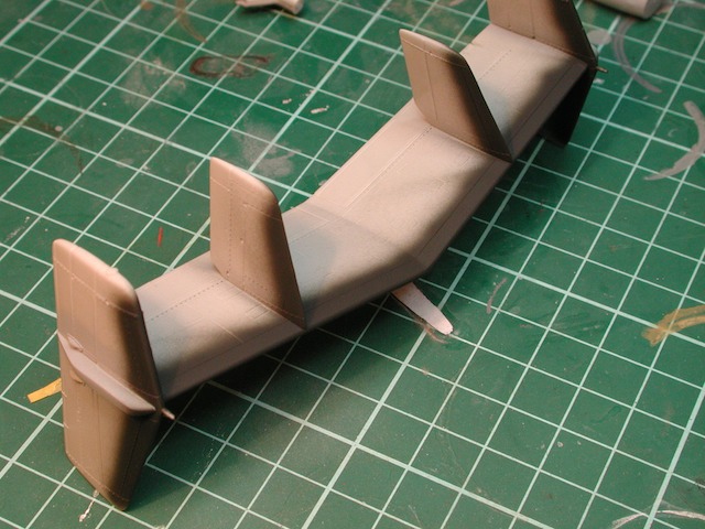
Black has also been applied to the nose for the anti-glare panel

Lastly, the resin wings have been painted with the safety red and leading edge black

With the flap area masked and the nacelles complete, its time to attach them to the wing

A quick dry fit to the fuselage to ensure everything lines up correctly

Possibly the worst joint in the kit is the nacelle to wing. Of course this wil be a pain to fix without losing panel line details.

Setting to work to fix the poor fit of the engines to the wings, I first applied a layer of super glue over the join. The glue was built up using several coats of super glue as the two parts not only had gaps, but a step between them

The super glue was accelerated with some kicker and then sanding took place. Unfortunately I could not save the panel detail on the wing edge however, I used some tape to protect what detail I could

Leaving the super glue to cure hard for 24hrs, I then rescribed the panel lines and applied a coat of primer. All things considered, I think this was a pretty good save

With the leading edges of the tail painted black (Tamiya Nato Black), the task of masking took place. Not too tricky, just time consuming

With the first round of masking done, the blue color has been sprayed. The Hasegawa paint instructions suggest Gunze H328 Blue, which is what I used and I think its a pretty good match for the real aircraft

The anti-glare and nose tip have been masked to protect the black

A little while ago, I noticed that the rotordome mount had 4 small blade antenna on each side. On closer inspection of my reference, it became clear that these antenna are not blades at all, but rather loops. I had decided that in 1/72, what Hasegawa had provided looked ok. Well, tonight I changed my mind

Using several lengths of 10thou brass rod, I bent, drilled and glued replacements for all 8 antenna. Its only a small thing, but I think its worth the extra effort

Last step tonight was to join the wings to the fuselage. The fit is very good, so I'm confident that not too much repair work will be needed

Some small amount of sanding and filler was needed to tidy up the rear join of the wing to fuselage join

With the wing to fuselage join secure, I next wanted to dry fit the undercarriage to enable me to test fit the crew entry door. I was then able to adjust the angle of the door to the correct height above the ground
With the blue on the tail dry, its time for mask up the four tail sections. This is slow, detailed work, but worth the effort to get a sharp demarcation

The bottom of the E-2 has many antennae. Hasegawa has provided each one in a realistic scale size. Here we see the rear fuselage

The forward lower fuselage with its antennae is also complete. The hole closest to the nose wheel well is for a navigation light, which will be added after final painting
In preparation for painting, the crew entry doorway has been masked

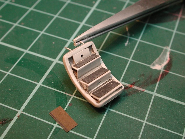
With the angle for the steps now marked on the door, my efforts turn to scratchbuilding the interior detail

The finished steps, made from 10thou card. I'm fairly happy with the end result. Working in 1/72 required me to use my magnifying lamp and glasses a lot

By chance, I was looking on airliners.net for some shots of the underside of an E-2 and found a very good one (E-2C on Airliners.net). I noticed that on the underside of the flaps, directly behind each engine exhaust, was a protective metal plate. It was obvious from the photo that the protective panel was inboard of the wingfold break in the flaps. It was at this point that the penny dropped and I realised that Wolfpack had made a significant error in their flaps. You can clearly see from the picture above that the Wolfpack flaps have been cut thru the metal plate, when my research indicates the plate needs to be entirely on the inboard section of the flap break

I decided the whole resin flaps needed closer scrutiny. To my further surprise, it seems a large section of the flaps have been removed by Wolfpack (or the resin has shrunk that much). Anyway, it was becoming obvious to me, that the resin flaps had to get chucked

With the decision made to fashion my own break in the flaps using the kit parts, I turned to all my reference material and also found that whilst the flap break on the lower surface was straight (along the edge of the metal plate as discussed above), the break on the upper surface was offset vertically and at an angle. Now when I think about it, this makes sense and the wingfold itself is angled, so why not the flaps. This picture shows the location and angle I chose for the split. Compare this to the size of the resin flap (in red)

With the cuts made, and the parts glued together, you can start to see what I mean about the angle of the join. The resin flaps turned out to be wrong in so many ways I can't believe I did not check them earlier. Oh well, live and learn

Here we see the top of both left and right flaps. The ends have been skinned with 10thou plastic card

In this picture we see the bottom of each flap. You can see that the protective metal plate is located on the inboard flap. I was a bit nervous that by changing the position of the split that the rest of the wingfold parts may not fit correctly with these new flap dimensions. To my relief, it all fits nicely and looks so much closer to the real aircraft.

One last photo to show the Wolfpack flap split solution (lower) and my solution using the kit plastic flaps (upper).

With the flap saga mostly over, my attention returned to completing the main fuselage assembly in preparation for painting. I decided to attach the rotordome mount as I think the decaling will not be affected by it being in place. I was actually surprised that I found myself ready to apply the main paint colour. I had been diligently working away that it kinda snuck up on me. Anyway, modern E-2C's are pretty easy to paint as they are all over one color and that color is FS16440 Light Gull Gray.

Hasegawa calls out Gunze H315 as the right match, which on the color chart is correct. In the Humbrol range, this translates to H129. When I did some test sprays with both these paints, I felt they were too dark out of the bottle, with the Gunze paint a closer match to the photos I had seen of operational E-2C's. Following some experimentation with adding white, I settled on a custom blend of H315 and H1 Gloss White. As both paints were gloss, I mixed extra thinners (General Purpose Thinners from Kmart) to ensure the paint would spray nicely. I'm happy with the end color, which will darken as I apply panel washes and weathering.

With the Gull Grey dry, I can remove the masking from the tail. Here I am testing the fit (looking for any gaps). All looks ok so far

I needed to touch up the white inside the wingfolds. Not wishing to make a mess with overspray, I have masked off the surrounding areas

The modified kit flaps are now ready for their red coat. After I took this photo, I decided to change the color of red I used, opting for Humbrol 60 (Scarlet) instead of the H174 (Signal Red) shown here. I chose to paint the red after the gull grey as the masking was much easier that way

The finished flaps. These will be quite visible on the finished model, so extra time and effort is well worth it

Small detail painting has now been completed with the black wing leading edges and the tail lock panel interiors

Decaling has commenced. This will be a pretty big job as the E-2 seems to have loads of decals and stencils

The Hasegawa decals have performed well. Where possible I like to trim the carrier film from kit decals (as they tend to be quite thick). As the Gull Grey paint was gloss I have not yet applied a coat of future. This was a mistake as the paint, in some cases, has reacted badly to the Micro Sol softening solution I have used on the decals. Live and learn

Wings and flaps have received their main decals. Stencils will be next (after that coat of Future)

With the decaling now complete, its time for the panel wash. I'm trying to tone down my panel lines and here I am trialling a grey wash in preference to my normal Burnt Umber

The panel wash is nearing completion. I like the effect on the engine nacelles, but perhaps the color is still too dark for the rest of the airframe

The crew entry door is now complete, with the last touch being the addition of non slip mats on each steps. This is made from small sections of 1200 grade wet n dry paper
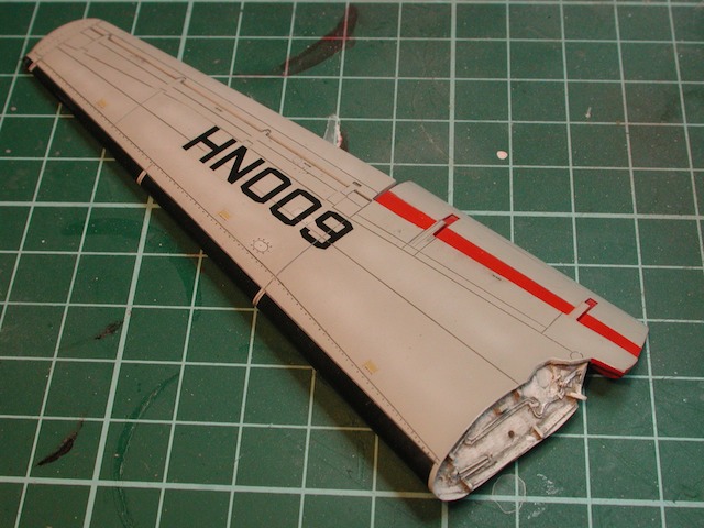
Here we see one of the finished wings. The flaps are fully extended when the wings are folded
Hasegawa provide the propeller leading edges as decals (which I experimented with and decided I could get a better result via painting). Here I a masking up the leading edges on all 16 blades.

More tape is needed to completely protect the blades from overspray

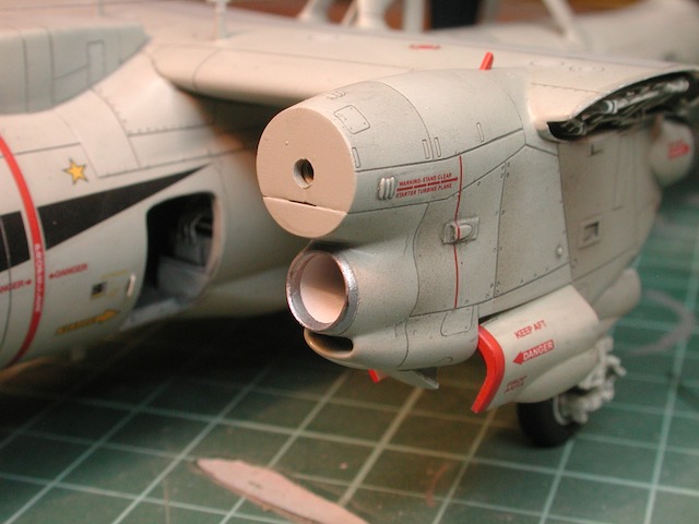
I was very restrained with the weathering on this model. the E-2's seem to be looked after very well by their crew and given this is a CAG bird it would be pretty clean. One area that seems to be universally dirty on all Hawkeyes is the engine nacelles. You should be able too see some dirty staining on the panels on the closest nacelle. This was done using Tamiya Smoke and a drop of Red Brown (XF10)

The undercarriage is nearing completion. A light wash of medium grey has been applied to highlight the nice details

A photo of the underside to show the details here. We don't see the bottom of models often

Final detailing and assembly is taking place. The masking has been removed and the undercarriage installed. Its starting to finally look like a Hawkeye

The final result of the engine intake trunking is quite good. However I'm now convinced that with the propellers installed, this will be pretty much hidden. Oh well, I know its there
One of the tasks I was not looking forward to was adding the wire antennae. In the end it was totally painless. I used "invisble thread", attached with super glue to reproduce the myriad of antennae the E-2 has

A close up to show the nose area and the cockpit "glass". The bulged side windows look "ok", but next E-2 I build I'll have to come up with a way to more accurately reproduce the mirror reflective finish on these windows

The rear section of the fuselage. The inboard flaps have been installed, as has the tail

All done !! A word of caution. All was good until I finally attached the radar dome. At this point, the model tipped back on its tail. Despite the amount of lead sinkers I put in the nose, the combined weight of the resin wings, tail and rotordome was all too much. Thinking quickly (after some colorful words), I decided to resolve this by dropping the tail hook. It looks believable and stops the little bugger from tail sitting

A photo from the rear quarter shows the wing fold and tail detail


